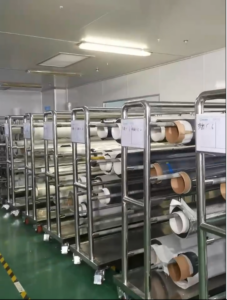
Cutting Smart Film PDLC (used in LCD displays, smart glass, etc.) requires balancing precision and efficiency, as edge quality directly impacts optical performance. Below is a structured guide to optimize the process:
-
1. Preparation and Tool Selection
Material Fixation & Alignment
- Secure the film on a vacuum adsorption platform or anti-static mat to prevent slippage.
- Use laser alignment markers or optical projectors to ensure the cutting direction aligns with the film’s layered structure (e.g., conductive layer, liquid crystal layer), minimizing delamination risks.
Tool Recommendations
- Precision Blades: Ultra-thin tungsten carbide blades (e.g., OLFA) for manual cutting. Replace blades frequently to avoid jagged edges.
- Laser Cutters: CO₂ lasers (10.6μm wavelength) are ideal for non-contact cutting. Adjust parameters based on film thickness:
- Example: 100μm PET-based film → Power: 30W, Speed: 10mm/s, Frequency: 1kHz.
- Die-Cutting Machines: Suitable for mass production. Optimize steel mold angles (25°–30°) and pressure (0.3–0.5MPa) to prevent deformation.
2. Cutting Process Optimization
- Environmental Control
- Maintain temperature at 20–25°C and humidity at 40–60% to avoid thermal expansion or moisture-induced dimensional errors.
Path Planning & Edge Quality
- Use vector-based continuous cutting paths in CAD designs to minimize start-stop marks.
- For complex shapes, design micro-connection points (0.1–0.2mm uncut areas) to simplify waste removal.
- Post-cut edge treatment: Polish with 2000+ grit sandpaper or use plasma treatment to eliminate burrs.
3. Automation and Smart Technologies
- Machine Vision Systems: CCD cameras enable edge detection with ±0.05mm accuracy.
- Parameterized Programming: Pre-set cutting parameters for common film thicknesses (50–200μm) and integrate robotic arms for roll-to-roll production.
- Real-Time Monitoring: Force sensors adjust blade pressure dynamically to prevent over-cutting or incomplete cuts.
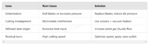
4. Troubleshooting Common Issues
5. Quality Inspection and Post-Processing
- Optical Testing: Use a transmissometer to check for uniform light transmission. Polarizer rotation tests reveal edge defects (e.g., light leakage).
- Functional Verification: Sample electrical testing to ensure response time <1 second. Damaged electrodes from poor cuts may cause circuit failures.
Final Notes:
- For small batches, prioritize manual techniques with sharp blades and meticulous alignment.
- Automated systems excel in high-volume production but require rigorous parameter calibration.
- Always combine optical and electrical tests to validate performance.
Adopting these strategies ensures efficient, high-precision cutting while maintaining the functional integrity of Intelligent Film .
Post time: April 27th 2025